The harmonic frequency in a power system is the positive integer multiple of the fundamental frequency. As a result, the third harmonic frequency is three times the fundamental frequency. Power factor (PF) refers to the ratio of working power in watts (KW) to perceived power in kilovolt amperes (KVA).
Many Power utilities in India are billing their industrial and commercial consumers based on Active Energy Consumption (Kwh) along with fixed charges and other charges. KWH consumption, when multiplied by the applicable tariff for the consumer will give energy charges payable by the consumer. The effect of reactive energy is considered through power factor penalty/incentives that vary from state to state across India.
In Maharashtra state, the consumers are charged based on kVAh consumption combining kWAh & kVArh, an extract from the MSEDCL circular is attached for further information. The prime objective of kVAh based billing is to encourage the consumers to maintain near unity power factor to achieve energy loss reduction, improve system stability, PQ services, and voltage profile.
Many industrial and commercial facilities can reduce their active energy (kWA) and apparent energy (kVAh) charges by reducing the current dependence on wattage losses in their distribution system. The major factors that contribute to high wattage losses in a network are explained in this article. These wattage losses can be reduced by improving the power factor closer to unity and reducing the voltage and current harmonic distortion below 5%.
The average wattage losses in a typical industrial facility can be 15-20 % of the total demanded power. This would mean substantial savings on Electricity bill charges depending on the kVAh or Kwh based Tariff structure and penalty/ incentives based on power factor or lag/lead reactive energy (kVArh) consumption.
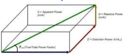
The Power factor value computed by utilities for penalty/incentive is called the Total Power Factor. The Total power factor has 2 components, namely the Displacement Power factor and Distortion Power factor, as shown below.
True/Total PF = Displacement PF * Distortion Factor
The distortion power factor is influenced by the harmonic inside the network, and reducing harmonic ranges can improve the overall strength factor and reduce the cost of power.
The following list is a simplified overview of several of the more crucial loss factors in an industrial or commercial facility, including a broad range estimate of reasonable loss values attributable to each stated effect. All these losses are current-dependent and can be readily mitigated by reducing the facility's current load.
HYSTERESIS LOSSES
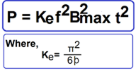
Current flow in forward and reverse directions leading to hysteresis loss as the core is magnetized and demagnetized. Hysteresis losses increase proportionally to frequency, as the magnetic particles of the center tend to align with the changing direction of a magnetic field. A magnetic particle's attempt to align itself with the magnetic field produces molecular friction as it moves continuously. The energy to accomplish this realignment of the magnetic domains comes from the input power and is not transferred to the secondary winding. Therefore, it is a loss and results in heat.
Typical hysteresis losses as a percentage of Power Demand: 1% -2%EDDY-CURRENT LOSSES
Eddy's current losses result from Faraday's law. No matter how a coil's magnetic field is created, any change in its environment induces a voltage in the coil. The induced EMF will cause a circulating current called Eddy’s current, proportional to the square of frequency based on the resistivity of the current path. The power loss in any electrical circuit is equal to the square of the current times the resistance. When an eddy’s current is present, it manifests itself as heat, contributing to the maximum operating temperature of the equipment.
Eddy's current losses can be found in protective circuit breakers, lighting ballasts, power supply transformers, magnetic motor starters, voltage reducing or isolation transformers, current overload relays, control contactors, and relays. All motor windings, and even building wiring when the wiring is near steel or iron structures, such as electrical enclosures, distribution panels, or pipework.
Typical eddy current losses as a percentage of Power demand: 2 % to 3%SKIN EFFECT LOSSES
When an AC is applied to a conductor, the current concentrates near the surface of the conductor. This is because the alternating magnetic flux produced by an alternating current interacts with the conductor, causing a back EMF that tends to diminish the conductor's current. The lines of force are higher at the center of the conductor and decrease at the edges making the effective area for current flow lesser increase the overall resistance of the conductor and higher watt losses. Harmonic loading increases skin effect losses by the square of the increase in frequency above nominal line frequency. It is responsible for a substantially lost wattage in any facility with large populations of nonlinear equipment loads, such as VFDs, DC drives, rectifiers, induction heating, or other arcing or switching power supply devices.
When an AC is applied to a conductor, the current concentrates near the surface of the conductor. This is because the alternating magnetic flux produced by an alternating current interacts with the conductor, causing a back EMF that tends to diminish the conductor's current. The lines of force are higher at the center of the conductor and decrease at the edges making the effective area for current flow lesser increase the overall resistance of the conductor and higher watt losses. Harmonic loading increases skin effect losses by the square of the increase in frequency above nominal line frequency. It is responsible for a substantially lost wattage in any facility with large populations of nonlinear equipment loads, such as VFDs, DC drives, rectifiers, induction heating, or other arcing or switching power supply devices.
Typical skin effect losses as a percentage of Power demand: 2% to 4%PROXIMITY EFFECT LOSSES
The proximity effect is similar to the skin effect. With the skin effect, the current distribution is affected by the conductor’s magnetic field, increasing the losses. The proximity effect is caused by the mutual influence of multiple current-carrying conductors. Their interaction causes uneven current distribution in the conductors, again increasing the losses.
Typical proximity effect losses as a percentage of Power demand: 2% to 3%TRANSFORMER LOSSES
Transformers are normally designed and built for use at rated frequency and sinusoidal load current. A non-linear load on a transformer leads to harmonic power losses that cause increased operational costs and additional heating in transformer parts. It leads to higher losses, early fatigue of insulation, premature failure, and reduction of the useful life of the transformer.
The two primary types of transformer losses are core losses and load losses. The core losses occur in the Transformer core by magnetizing current and mainly include Hysteresis losses and Eddy current losses. Transformer depends on the quality of core lamination and the latter on the thickness and resistance of the core used to construct the core. The Harmonic voltages are responsible for iron losses due to hysteresis
Stray losses are also called iron losses. Stray losses are additional eddy current losses in the structural parts and within the winding produced by Leakage flux and cause hot spots in the winding.
A Transformer loses load when it is loaded, and the loss is proportional to the square of the magnitude of the load.
Three categories of load loss occur in transformers:
Resistive losses are often referred to as I2R losses. Eddy-current winding losses due to the alternating leakage-fluxes Stray losses in leads, core-framework, and tank due to the action of load-dependent stray alternating fluxes.
The term resistive losses refer to losses resulting from windings that cannot be produced without electrical resistance (at least until superconductors are successfully developed) and are therefore a "fact of life" that cannot be avoided.
The leakage-flux occurring in transformer windings is greatest at the winding ends but is present throughout the entire winding body. Consequential eddy currents are set up that oppose the natural direction of current flow and enormously increase the transformer’s apparent AC resistance.
Stray losses occur in all transformers, although they are more common in larger transformers due to the physical size of the leads and the currents they transport.
Harmonic currents traveling through transformers enhance eddy current losses and load losses, whereas harmonic voltages produce hysteresis losses. The load losses are thought to arise at the square of THDi (current THD), while core losses increase linearly with THDi (Voltage THD)
Typical transformer losses as a percentage of Power Demand: 2% to 5%LINE LOSSES
In addition to I2R losses and dielectric losses, cables have other losses such as skin effect and proximity-effect developed by magnetic induction. The proximity effect is insignificant in single conductor cables where conductors are not working close to one other. These numerous loss effects can add up to a significant amount in a typical industrial conduit encased distribution system. The harmonic currents can increase the apparent AC resistance to more than an order of magnitude above nominal DC resistance values.
Note that I2R losses occur in ALL distribution system conducting components, not just the cables.
Typical transformer losses as a percentage of Power Demand: 1% to 3%Motors, lighting systems, wiring, mechanical terminations, distribution panels, protective devices, transformers, switchgear, and all end of circuit equipment face a range of resistance increasing inefficiencies in an industrial/commercial site, resulting in substantial wattage loss.
Identifying and calculating such loss components is a challenging engineering specialty. The Power quality experts at Jef Techno Solutions have extensive experience and knowledge of all the factors affecting the operating efficiencies of each of these components. Our Power Quality service team uses cutting-edge test and analysis equipment to assess the electrical system. The Losses on-site and offer solutions to minimize actual current, reactive current, and harmonic current, resulting in cost savings and quick payback for our valued customers.
EXTRACTS OF MSEDCL ELECTRICITY TARIFF, EFFECTIVE 1ST SEPTEMBER 2018.
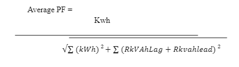
The formula adopted by MSEDCL for computation of PF, which violates the formula directed by the Commission is reproduced as under.
On MSEDCL's website, the company has published the following guidelines for the execution of PF under the new formula.
a) If PF level is less than 0.90, then penalty shall be as per percentage given in MERC order.
b) If the PF level is higher than 0.95, and RKVAh lag consumption is higher than RKVAh lead consumption, then the PF incentives shall be given as per MERC order.
c) If the PF level is higher than 0.95, and KVAh Lag consumption is less than RKVAh lead consumption, then the incentives shall not be applicable.
d) If the RKVAh lead reading is not available, then the old procedure of the PF computation will be followed.
As per the provisions of CEA (Technical Standards of Grid Connectivity) Regulation - Part IV dated 21-02-2007, it is mandatory for Distribution Licensees and Bulk Consumers to maintain PF above 0.95 to provide sufficient reactive compensation for their inductive loads. PF above 0.95 means it is for both lead and lag.